Wednesday, January 30, 2013

Flashing Yellow Arrow Operation

This is a complete revision of a previous post on the same topic.  Based on new information, many of the controller settings were modified as shown below:

The operation detailed in this post is not a recommended operation, it is provided to allow engineers who work on traffic signal controllers ideas as to how Flashing Yellow Arrow signals could be operated.

The operation in this post details controller operations where the signal will not provide a FYA indication across a pedestrian movement that has a WALK or FDW indication that is active.

Flashing Yellow Arrow Operation

The Naztec controller has some specific things that must be done in order, to enable FYA.  The manual has some of the information, but not all.
 
One key piece of information is that the manual (as of December 2012 V.76, and Technote 1105 on the Naztec Website specifically use Overlap 1 (OLA) as the example overlap detailing the controller settings.  According to the Naztec rep’s email on January 21, 2013, the overlaps with FYA operation need to be on even overlaps (OL2, OL4, OL6… OL16), not on odd overlaps (OL1, OL3, OL5… OL 15).
 
When the FYA overlaps are on odd overlaps, the FYA appears to work properly until a preempt call is served.  The preempt call causes the signal that is operating on FYA to present signal indications that the monitor will not accept.

This appears to occur very occasionally in signals that are running in STD mode, operating with FYA indications.  However, when the signal is operating as described below, for No FYA across Ped Movements, the preempt call regularly presents signal indications that the monitor will not accept.

When the overlaps are mapped to even overlap numbers, the normal termination of a FYA operation due to a side street call, the signal should transition something like:


The main street greens (phases 2 and 6) and the main street FYA indications (phases 1 and 5) should all go yellow simultaneously upon the call to the side street.

When the overlaps are mapped to odd overlap numbers, the normal termination of the main street to a vehicle or pedestrian call on the side street operates the same as the above diagram, at least in Apogee V.76.7D, Build 3195, however when an emergency vehicle preemption call is served, the following phase operation will occasionally occur when the controller is in STD mode, but predictably occur when the controller is in USER mode:


The monitor will not accept a steady yellow on load switches 1 and 5, while greens are on for load switches 2 and 6, causing the signal to go into red flash.
By programming the overlaps running the FYA as even numbered overlaps, the controller has internal logic on the even numbered overlaps that prevent this from occurring.

No FYA across Ped Movements

The operation described here includes specific modifications of the controller operation to have the signal stop presenting a FYA indication to the left turn, when the pedestrian immediately to the left of the driver in the left turn pocket could have a WALK or FDW during normal operation.

A standard operation would be to allow the pedestrian movement to go to WALK and FDW while the corresponding left was in FYA.  In other words, if the NBL signal was in FYA operation, the SB ped would be given the WALK and FDW.

At issue here is what level of safety needs to be provided to the pedestrian while the driver is looking at for gaps in the oncoming stream of vehicles.  It could be argued that the left turning driver should yield to pedestrians to their left, however, if the pedestrian is traveling thru the crosswalk, to the left of the driver, going the same direction as a driver, the left turning driver may never look behind them while attempting to turn left for a person walking, running, biking or using other mode of transport while crossing the crosswalk.

Another operation would be to allow the FYA to terminate, and go to a steady red arrow, when a pedestrian received a WALK / FDW for the crossing.  This would likely create a yellow trap for the driver at a 4-legged intersection.

This operation would receive the pedestrian call, and wait for the signal to gap out, or max out on the main street traffic, then quickly serve the side street, them come back to the main street with the Ped WALK, and the conflicting left turn having a red arrow.

This is done by modifying the signal operation from the standard 8 phase dual quad operation.

Modifying the Phase Sequence


The following example is for setting up FYA for an intersection with the following basic operation:

The flashing yellow arrow will be for the eastbound left movement (Overlap 12 corresponding to Phase 1), and for the westbound left movement (Overlap 14 corresponding to phase 5).

The actual phase diagram is as follows:


The modified ring and barrier structure is set up to allow the FYA to flash yellow with the thru movements (1 with 6), but not with the peds (1 with 10).

The correspondence of the overlaps, and outputs is as follows:
 
The FYA output to the field wires is set up to connect to the (typically) unused yellow indication on the pedestrian load switches.  In this case, LS 9 drives Ped 2, and LS 11 drives Ped 6
  

Setting the Ring and Barrier Operation on Apogee V.76

 
There are several areas that need to be set up to make the FYA work.

The signal must be set to User mode.  To do this, go to MM-1-7, and turn the Run-Enable Status from ON to OFF, press enter, and the signal will stop running.  Next, go to MM-1-2-1 (Unit Parameters) and change the Phase Mode from “STD8” to “USER”. 

Now the ring and barrier structure must be modified to include the extra phases.   This is done via the signal sequence (MM-1-2-4):
  
The example here shows only modifying Sequence 1, but the user may want to modify other sequences.  

In general, when I am programming a special sequence that I don’t want to have the ability to undermine with potentially calling a sequence that may violate antibackup, or other features, I copy the only sequence I want to use into all 16 sequence entries, which means that there should be no way to have a sequence that creates a problem for the signal operation.

Next, the phase concurrency table needs to be modified to reflect the modified phases.  At this time, the signal is also modified such that it starts up in 9 and 10 WALK.  Normally, I start up signals in main street WALK.

This is done under MM-1-1-4:


Now that the ring and barrier structure is set for the controller, the signal run timer can be turned back on, under MM-1-7

Enabling the Specific Vehicle and Pedestrian Movements

  
The specific phases need to be enabled under MM-1-1-2.  The normal phases are enabled for the ped movements, plus phases 9 and 11 need to be enabled, so that the peds will time.

Time needs to be added to phase 9 and 11 peds under MM-1-1-1.  Also, any time for WALK and FDW for phase 2 and 6 peds need to be zeroed out.  In the example below, the ped timing, yellows and reds are what are operating in the signal cabinet for the intersection.

Specific timing is added to phase 9 and 11 for the min green, yellow and red.  This time is added, since the signal will be operating in soft recall during certain hours of the day.  Without having the appropriate clearance times for the phase 9 and 11, and the signal in soft recall, a late night pedestrian service may terminate from the main street to the side street at the end of the FDW without the signal going through the appropriate clearance times for the main street traffic.

 
Now the ped timing for phase 2 and 6 peds needs to be zeroed out.  The Peds that are normally associated with phase 2 and 6 are now phase 9 and 10 peds respectively.

Setting The Load Switches for the Overlaps


Now the load switches must be assigned for the overlaps.  The Channel I/O needs to be modified as follows under MM-1-8-1:

If you scroll to the right of the last column on the first screen , you will see the second screen that covers load switches 9 through 16.

The assumption on this second screen is that the channels were already modified so that the pedestrian load switch and overlap load switch assignments were modified to reflect that the peds were on load switch positions 9-12 and the standard overlaps were on load switch positions 13-16.

In this case, the load switches for 13-16 were actually modified to an unused input (changed to OL 16).  This was done to make sure that there was no problem with the overlaps being assigned to load switches 1, 2, 5 and 6.  Each specific installation will need to assign overlaps to the unused load switches that will not conflict with the other inputs.  Alternately, the unused load switches could be programmed to channel 0, which will result in a dark output.  The monitor will need to be programmed to accept a dark red output if the unused load switches are programmed to channel 0.

Setting up the Overlaps


There are several overlaps to be programmed for this operation.
  • Overlap 12 and 14 are for the flashing yellow arrow.
  • Overlap 9 is for the westbound thru / right movement
  • Overlap 10 is for the eastbound thru / right movement
Starting with Overlap 9, the following parameters need to be programmed under MM-1-5-2-(9-Enter)-1:


For Overlap 10, the following parameters need to be programmed under MM-1-5-2-(10-Enter)-1:

Setting up the Overlaps for FYA Operation

For overlap 12, several parameters need to be added, including the type of overlap.  This is programmed under MM-1-5-2-(12-Enter)-1


The minus ped overlap parameters should not need to be programmed, However, if it is desired to program the negative ped overlaps, then this done under MM-1-5-2-(12-Enter)-2

For overlap 14, similar programming needs to be entered into the controller.  This is programmed under MM-1-5-2-(14-Enter)-1

The minus ped overlap parameters should not need to be programmed, However, if it is desired to program the negative ped overlaps, then this done under MM-1-5-2-(14-Enter)-2

Setting The Ped Yellows on Load Switches for FYA


Under MM-1-8-1, some values need to be modified for the output drivers.  In this case, the normal vehicle head for phase 1 (Channel 1) will be changed to run from Overlap 12 and the normal vehicle head for phase 5 (channel 5) will be changed to run from Overlap 14.

Now the controller’s operation needs to be modified to allow the overlap setting work with the controller outputs.  This is done by modifying the Channel plus parameters, under MM-1-8-4.  Once you are at the screen, scroll to the right, to bring up the screen that shows channels 9 through 16.  Modify the settings as follows:

This screen allows the controller to override yellow indications on load switches 9 and 11 to flash yellow as a driven output.  Normally, the yellows on the pedestrian load switches are steady on during the FDW clearance phase.  The steady on is a NEMA TS2 output standard.  This screen is the final item in the controller that must be enabled to get the controller to flash the ped yellow outputs, to drive the flashing yellow circuit on the left turns.

Setting the Pedestrian Calls and Detection Diagnostics

  
Now the pedestrian need to be modified to allow for to allow the pedestrians for phases 9 and 11 be mapped to the phase 2 and 6 inputs.  This is done under MM-5-4

Note that the MaxPres column has values other than zero.  Setting a value to other than zero for the MaxPres allows the controller to look for malfunctioning pedestrian buttons – where they are locked on.  This is covered in more detail at: 

Setting Antibackup Operation

  
Now the antibackup feature needs to be set up, so that a ped call on phase 9 does not back up with a FYA on phase 5, nor a ped call on phase 11 does not back up to a FYA on phase 1.

The antibackup coding done via MM-1-1-5

Essentially, all of the work in the controller allows for the FYA to not operate across the pedestrian yellow

Setting Logic Processor To Serve the Side Street Before Serving Peds


One last thing needs to be done to the controller to allow the signal to cycle back to the pedestrian.  This is especially important to enable since the side street may have no traffic.  This is done by creating two logic statements to cause the signal to call a (typically) unused detector, and the detector then looks for an opportunity to call the side street.

The logic statements are coded under MM-1-8-7


 A quick conversion, from Section 12.6 and 12.7 of the Naztec controller manual
  • I 64         (detector 64)
  • I 130       (Ped call 2)  - The ped call is actually ped phase 9, but the physical input is 2 
  • I 134       (Ped call 6) –  The ped call is actually ped phase 10, but the physical input is 6
  • I 240       (logic flag)
  • I 241       (logic flag)
  • O 90       (Phase 2 on)
  • O 94       (Phase 6 on)
Keep in mind, if you are coding this in ATMS.now, the columns in the data input screen in ATMS.now do not coincide with the columns in the controller.
 
Something to keep in mind about the logic processor.  The controller processes the logic from top to bottom.  The logic flags are set up to allow the controller to allow either ped

Setting Logic Processor To Serve the Side Street Before Serving Peds

  
The last controller function to set is to create a dummy input for detection channel to call phase 4 (the side street phase).  In this case, I selected detector input 64.  This detector input is unlikely to be used in normal operation.  If the controller operations use input 64 for a specific detection input purpose, then another detector should be selected.

Set detector 64 to call phase 4 under MM-5-1

Set detector 64 to be a calling detector, and to be a locking detector for red and yellow operation under MM 5 2.

Something to keep in mind about the logic processor.  The controller processes the logic from top to bottom.  The logic flags are set up to allow the controller to allow either ped call to serve the locking call to the side street.  Another way to reduce the logic statements by 1 line would be to have two unused detector channels used to place the call to the side street.

The logic statements could also be coded under MM-1-8-7

In this case, both detector inputs 63 and 64 would be coded to place locking calls to phase 4.

Emergency Vehicle Preemption Operation


The EVP channels on the approaches with the FYA operation should be set under MM-3-(EVP channel <enter>)- 8 to turn on the All Red B4 Prmpt.  The factory configuration has this off.
 
If the all red before preempt is not turned on, then an EVP call on the approach will create a yellow trap for vehicles in the left turn pocket when the signal transitions to preemption.
 
As stated before, if the overlaps are on odd numbers and the controller is running in USER mode, it is quite likely that any EVP call will cause the controller to transition where the monitor sees steady greens on the main street thru phases, and steady yellows on the main street left turn phases – which is a conflict.  As of Apogee V.76.7D, it did not matter what particular EVP call, or if the all red before preempt was enabled, any EVP call would cause the signal to display the conflicting greens and yellows while the FYA overlaps are programmed to the odd phases.
 
The EVP channels need to be programmed for the appropriate phase and overlap operation.  
 
The overlap exit phases can be tricky.  Normally, the EVP channels are programmed to end the call on any approach with the main street green thru’s (in this case phase 2 and 6).
 
This creates a problem, when the signal controller is programmed for anti-backup on phases 2 and 6.  When the EVP call ends, and the signal transitions from any EVP to 2 and 6, it does just that, without reliably bringing up the FYA indications that correspond with the phase 2 and 6 operation.
 
In general, the EVP operation and end of phase is programmed for this signal as follows:
 
 
By exiting the side street EVP call to the same phase, the controller will come around to the next movement, which is likely 2 and 6 including the FYA for corresponding lefts.
 
By existing the main street EVP call to the main street lefts, the controller will quickly transition to the main street green with the FYA active.

Min or Soft Recall

Once the controller has the programming as shown above, one final step needs to be made.  Phase 2 and 6 need to be in either min or soft recall.  Otherwise, under low traffic volumes, the signal will rest in phases 9 and 10, and the FYA will not turn on to the drivers.
 
Now, the monitor operation must be modified to allow the FYA to operate.
 

Settings in the Reno 1600 MMU for FYA

 
The monitor needs to be set up for the FYA operation.  In this case, phases 3 and 7 are future phases.  There are multiple methods for setting up the monitor based on how the load bay is being used.  This method is consistent with the programming of the Reno MMU Application Note AN-005 Example 3. This technote is available at Reno A&E’s website at:
 
 
The particular screens for the Reno monitor for this operation in the test cabinet is as follows:
 
A couple of things to note. 
 
Load switch 1 and 5 are the steady RYG arrows of the FYA head.  Load Switches 1 and 5 need to have field check / dual enables turned on in the monitor.  With this done, the monitor should internally compare the load switch outputs of the 3 arrows on the load switch, with the corresponding flashing yellow arrow on the same 4-section head.
 
A flash transfer relay can go bad, where the outputs of the FTR are always flashing.  In one specific case during testing, the bad FTR caused load switch 1 and 5 to flash red, while the signal was operating with the flashing yellow arrow flashing on the same 4-section head.  While the monitor was set up to not have load switch 1 and 5 enabled for field check / dual enables, the monitor found no problems with the dual flashing of the FYA and the errant red flashing due to the bad load switch.  Once the field check / dual enables were checked for load switch 1 and 5, the monitor found the problem and kicked the signal into red flash.


Tuesday, January 15, 2013

Additional Thoughts on Pedestrian Detection

This is a continuation of a previous post, found at:

 http://ntcip-unleashed.blogspot.com/2012/02/pedestrian-detection-diagnostics.html

Generally, there are two pedestrian pushbuttons for each pedestrian phase.  These two inputs are wired in parallel to a single input.  The two buttons for phase 2 are wired in series to the input for ped phase 2.  This means that with most signals, the 8 pedestrian inputs are wired in pairs, to inputs 2, 4, 6 and 8.

Modern traffic signal controllers are capable of at least 8 pedestrian inputs.  Many are capable of 16 pedestrian inputs.  Traffic signal cabinets can be configured to include at least 8 pedestrian inputs.  Modern traffic signal controllers allow for mapping of any ped wire input to any controller ped input.  This can be done in two different places, one is in the mapping of the specific pins / BIU designation in the controller, and another in a pedestrian detection input screen.
Since normally the two pedestrian pushbuttons for any specific phase are wired in parallel to a single input, any problem on the parallel circuit will register in the pedestrian detection diagnostics as a failure on the ped phase input.  The parallel circuits for the two buttons creates a situation where the technician needs to spend extra time and effort to isolate which particular button / wire combination in the parallel circuit is failing.

Since multiple inputs can be mapped, the signal can be rewired to have each specific button / field wire set come into a unique input.  This would mean that when a failure occurred, the technician would have immediate knowledge of which particular button circuit was problematic.

A standard approach would need to be figured out.  A potential standard for the wiring could be:
Detection            Mapped               Near/Far
Input                     Phase
1                                 2                           Near
2                                 2                           Far
3                                 4                           Near
4                                 4                           Far
5                                 6                           Near
6                                 6                            Far
7                                 8                           Near
8                                 8                           Far

Where “Near” is the button closest to the approaching traffic on that that phase’s approach, and "Far" is on the opposite corner for the same phase.
This type of wiring, along with pedestrian detection diagnostics would allow for the central system to report the specific button that was failing.

This is important, as when ped detectors become stuck on, this causes added delay to the drivers waiting for pedestrians that don’t exist. 
Special consideration will need to be provided where there are more than 4 phases with pedestrian movements.  While most modern signal controllers include 16 ped inputs, not all modern signal controllers actually include data entry screens to map ped inputs 9 through 16 to anything, nor data entry screens to apply detection diagnostics to the ped inputs 9 through 16.
This type of approach will need to be clearly documented, and most importantly agreed to by the field technicians who will be implementing and using this type of approach.

Monday, August 20, 2012

A couple more thoughts about detection diagnostics

This is a continuation of the earlier post on detection diagnostics, at:

http://ntcip-unleashed.blogspot.com/2012/02/controller-detection-diagnostics.html

The detector settings need to be reviewed to make sure that the global settings are not creating undue consequences.

In one recent example, a left turn pocket had moderately high traffic volumes, and the stopbar detector was a 60-ft long quadrapole.  The length of the quadrapole created a situation where there was never a gap in the traffic, so the standard stopbar (standing queue expected) timing of 5 minutes max time / 10 seconds detector fail time, created a situation where the timer for the left turn signal gapped out cycle after cycle.

This was not a new signal, but one where the operation had been changed from one brand of signal to another brand of signal as a part of a systemwide upgrade.  The settings were consistent with the previous brand's operation, but some changes were made in the conversion.

In looking at the new operation, it appeared that the signal was gapping out consistently, but there was a static queue forming.  The signal was gapping out because the detector fail mode was only placing a call for 10 seconds, and if the traffic was over the advanced detector, then the siganl would extend for time beyond the 10 seconds.

After observing the operation for a short while, it was apparent that the signal was not getting enough time for the movement.  Determing the reason for this operation was complicated by the fact that the 60-ft quadrapole also had NTCIP Queue mode turned on.

The detector diagnostics operate on the raw feed of the detector into the controller, not on the processed controller operations of the detector.

After observing the left turn pocket's operation via video feed, some modifications were made to the detector diagnostics from 5 minutes max time / 10 seconds detector fail time, to 15 minutes max time / 20 seconds fail time.

Once the timing changes were made, the left turn pocket cleared out in a few cycles, and began operating as expected.

The moral of the story is that the signal operation needs to be monitored after changes are made.

Friday, August 10, 2012

Why Communicate To Your Signals.


This may seem obvious.  But what needs to be communicated with?  What is appropriate to spend the extra money to purchase the optional Ethernet port on?  When two products are available that meet the specification, and one has data logging capabilities (and costs more), is it worth getting the device with the data logging?

Controller Communications

This is the most obvious one to connect.  Connecting the controller allows for remote uploading and downloading of the controller database, plus monitoring of the controller’s current operation.  If the signal system includes a central system, then the signal can be configured to provide data on scheduled intervals back to the central system.

The data fed to the central system can include alarms, traffic counts, current status of the controller (what phases are green, yellow, red etc.) and other information.  In some cases, the central system can be set up to log this data.  The central system that I use logs a great deal of information.  

One key piece of information that is logged, is the time served for each split division.  This is done whether the signal is in coordination, or free.  This is logged as historical information, so it is easy to run a report to look at what was happening recently for the amount of time served for any or all movements at the signal.  This can be helpful to determine what a reasonable cycle time may be for a signal.  It can also be helpful in determining if there is a problem with a signal.  Citizens will call and make statements about long waits for a green, or that a green was never served for a side street.  I have had phone calls where a citizen stated that they waited 25 minutes for a green.  There may be some truth to that statement, but having the ability to look back on the split division logs allows me to confirm that there was, or was not a problem at the specific time that the citizen stated that they had the undue wait.

The logging of data also helps identify problems with the signal operation.  If a controller develops internal problems, that information may be part of the alarm stream that is reported back to the signal.  We recently had a controller develop a problem with the TS2 communications and the controller started showing thousands of SDLC detector failures an hour.  Since the detector failures are not a critical SDLC problem for the controller, the signal kept chugging along.  A quick review of the alarm logs showed that there was a problem with the signal.  The problem was manifesting itself by causing the signal to extend, and serve movements that had no cars.  Based on the field review of the equipment, it was determined that there was a problem with the controller, and the controller was swapped out.  The BIU’s were swapped out, and the problem continued.  The problem could have been the CPU or the SDLC communications on the 2070-2N connector.  Bench testing will help determine that.  But having the controller connected to the central system gave us the first piece of information that there was a problem.

Another key piece of information is when a signal goes into all-red flash.  When a signal goes into red flash, the central system knows this within a second or two, and within another few seconds the central system sends out an email to key personnel stating that the signal is in red flash.  In some cases, I have seen signals in red flash for several days before a citizen calls in the problem.

Monitor Communications

There is a new generation of monitors generally called smart monitors.  These include advanced features for data logging, communications ports, and special programming to accommodate things like flashing yellow arrow configurations.  Many agencies are still holding on to their old monitors.  The old monitors work, but may not provide the same level of information that the more modern monitors provide.

I have had citizen calls where the citizen states that they are waiting at an intersection, and they are never getting a green.  By checking on the central system, I can see what the system states the controller is telling the system.  By checking remotely on the monitor software, I can confirm that the field indications are consistent with the central system.  

The monitor software allows for remote viewing of the signal inputs and outputs, along with the line voltages.  The picture below shows the Reno AE software talking to a Reno 1600Ge MMU.  This is a static picture, so you can’t get a real feel for the information.  The line voltages are dynamically being updated.  The current greens, yellows and reds are showing up on the screen.

Reno A&E PC software view of monitor operation

Another feature of the monitor software is that when a signal goes into flash, the monitor software can provide very good information about why the signal is in flash.  Is the problem a controller issue, a cabinet issue – that requires somebody to replace a component in the signal cabinet, or a problem with an indication that requires a bucket truck?

Problem Controllers

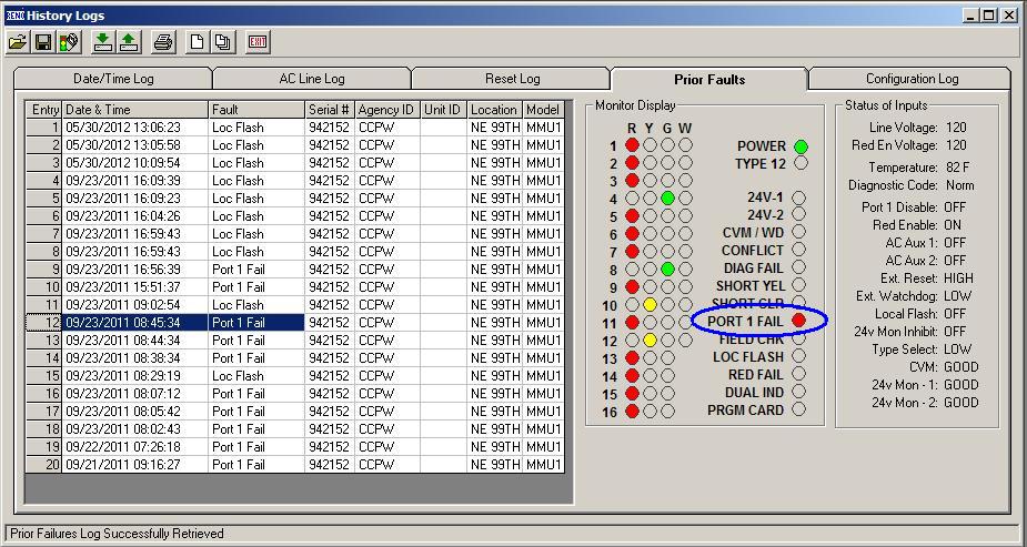
In the example below, the prior faults log is shown for a Reno 1600Ge MMU.  In this example, the controller CPU was dying. 


Reno MMU reporting a Port 1 failure
A little explanation of the standards is probably in order here.  The NEMA TS2 standards require that if a controller exhibits a Port 1 failure 3 or more times in a 24-hour period, that the monitor latch the signal in all-red flash.  The Port 1 is the main port out of the controller that provides the SDLC communications.  The controller sends out command frames, and gets response frames from the peripheral devices.  This is a very important communications node.  A Port 1 fail would typically be a failure of specific command frames from the controller.  These frames are generally routed around the controller, Terminals and Facilities (T&F, also known as the load bay) BIU’s and the MMU.  When a Port 1 failure occurs, the monitor puts the signal in flash.  If the Port 1 failure clears, the monitor will allow the controller to automatically come out of flash.  If 3 port 1 failures occur in a 24-hour period (also called in some controllers as 3 critical SDLC failures in 24 hours), then the monitor will transition the signal into all-red flash and keep it there until a technician comes by and services the cabinet.

Because the TS2 standard requires that 3 3 port 1 failures in 24 hours occur before the monitor locks the system in all-red flash, you can have a situation where the signal will transition in, and out of flash on its own.  This is not like a CVM fault, or 24V fault, where you can put in jumpers on the MMU board to latch a CVM or 24V fault.  This is a programming issue in the monitor.  To deal with this, many controller software packages allow the user to modify this by having the controller internally latch the signal in red flash when 1, 2 or 3 (user specified) Port 1 failures occur in a 24 hour period.  This will allow the controller to keep track of its own problems, and upon seeing a Port 1 failure, keep the signal in red flash.  This should allow the controller to not bounce in and out of red flash multiple times before going into locked red flash.

In the example above, the controller’s CPU was not working properly.  The controller would lock up, and create a Port 1 fail which the monitor reacted to, then the controller CPU would restart itself, then lock up, creating another Port 1 fail, restart and create another Port 1 fail, at which time the MMU would latch the red flash.

In the attached example, you can see that the controller went into red flash 3 times 8:38 AM and 8:45 AM, then a technician cleared the controller failures, restarted the controller, and the signal worked normally until it went into 2 Port 1 failures (in and out of red flash 2 times) between 3:51 PM and 4:56 PM.  This looks odd, because it looks like it went into red flash twice before it locked this time.  The reality is that I had a replacement CPU in my hand, and had just opened up the cabinet door at 4:56 PM, and the signal went through its restart procedure.  I then placed the signal into cabinet red flash, replaced the CPU, and restarted the signal with the new CPU.

Determining Conflicts

Another example of how the monitor software can help determine what is going on is when a conflict occurs.  In the example below, phases 2 and 6 were green, and the monitor showed that phases 3 and 4 showed green and reds on simultaneously.  This may not be the best example to show, but this was a case where one of the field technicians was working inside a cabinet, and momentarily contacted the greens for phase 3 and 4 to ground, which caused the signal to go into flash.

Reno MMU reporting a conflict
 While this may not be the best example, it does show information.  I got the email from the central system that the signal was in flash, and then almost immediately out of flash.  I pulled up the monitor PC software, and looked at what the monitor said it was doing.  By the time I got the monitor PC software running, the signal was out of flash.  I called the signal tech and asked what was going on.  He was a little sheepish, but told me what had happened.  Nobody got hurt, and the tech got a good reminder that you need to be careful when working around the contacts in a cabinet.
Oddities

One thing that you may see occasionally is the signal going into all-red flash because of a short yellow.  This is rare.  Most traffic signal controllers do not want to have a yellow change interval less than 3.0 seconds.  Some controllers will allow yellow change interval settings at less than 3.0 seconds, but only if the controller is programmed in one place to allow less than 3.0 seconds, and in another place to specifically program a phase to have less than 3.0 seconds.  I have been a traffic engineer for a long time, and have found exactly zero signals where I would time the signal at less than 3.0 seconds of yellow change interval.

The MMU also monitors the yellow change interval.  In the event that the yellow change interval is less than 2.7 seconds, the monitor will place the signal into all-red flash.  This can also be overwritten in the monitor settings, but like the short yellow in the controller, I have found exactly zero signals where I would override this setting in the field.

Below is an example from a traffic signal controller in a cabinet that is in a test environment.  This was forced to a short yellow as a part of testing out some features in the controller and monitor. 

If for some reason the signal actually experienced a yellow of 2.7 seconds or shorter, the signal would automatically go into all-red flash.

Reno MMU reporting a short yellow fault
Having the communications in the field allows the technician to know what has happened to the signal before leaving the desk.  This helps the technician to determine what level of equipment and expertise will be able to fix the problem.

The last example for monitors shows a known problem with the TS2 specification.  This is a minor irritant from a maintenance standpoint, but it may be a bigger deal if you are a pedestrian.


Reno MMU reporting dual indication fault
The NEMA TS2 specification requires that the monitor look at the time that the Flashing Don’t Walk (FDW) is on, and off.  The specification essentially requires that the FDW be turned on for half a second, then turned off for half a second.  The monitors generally allow for some slop in the SDLC communications frames, by allowing extension either of the on or off to 6/10th of a second.  This is because the controller is driving the outputs, and in the event that a frame is missed, the status of the indication won’t change.

Occasionally, the monitor will see the FDW on or off for 7/10th of a second.  This is seen as a problem by the monitor, and the monitor transitions the signal into all-red flash immediately.  This extra 1/10th of a second happens very rarely, but it happens.  In my experience, when a TS2-1 traffic signal is left in ped recall, this will occur about once a month, on one of the pedestrian movements that is in recall.

Video Detection Communications

Cameras fail.  Nature sometimes helps.  What appears to be a good viewing angle when you set it up may be very different at night, or in the rain.  

Cameras fail

The following three pictures show older generation cameras that have problems with the video feed images to the video processor.  When the cameras are not working properly, and feed bad information to the video processor, this defines the term “garbage in, garbage out”.

Problem camera.  Note that the picture is divided where the bottom of the screen shows the far advance, and the left side of the screen shows what should be on the right.  The video detection zones are correct, if the camera were working properly.

Problem camera.  Note how the picture is divided at the bottom of the screen.  The bottom of the screen shows what should be the far horizon of the camera.

Problem camera.  Note how the picture is divided about in the middle of the screen.  The bottom half of the picture should be above the top half.  The zones are correct, assuming that the camera is working properly
These cameras are being replaced.  The key here is, this signal was not connected to any system.  It was a lone signal, with no communications.  The only reason we knew about the problem is because a citizen got frustrated and called in that the signal wasn’t operating properly.  If this signal were connected to the system, we would have been able to look at the operation and see what was working properly and what wasn’t.
Once a week, or more frequently, I spend a chunk of time and pull up multiple signals and look at what they are doing.

In a past job, I found another unique type of problem.  The video detection was not working properly.  It didn’t take long to figure out what was causing the problem.  It probably would have taken a little less time, if I had already had my first cup of coffee before I started looking at the cameras.  In that situation, the video detection cameras were mounted on Astrobrac connections to the mastarms.  During the night, the Astrobrac straps slipped on the mastarm, and the camera swiveled from being on top of the mastarm to being on the bottom of the mastarm, hanging down instead of up.  This caused the camera to go from the normal looking at traffic approaching eastbound to the intersection, to upside down, looking at traffic departing the intersection westbound.  The stopbar detection that the camera was driving didn’t work so well.

Sometimes Nature Helps

Below is a video I took where we had a spider who created a web over the video detection camera lens.  You can see how the spider is causing false calls to the controller.


Below is a video of a poorly placed camera, but showing how the glare of headlights is causing false calls on the detectors.


The key here is to watch the detection zones for the cars traveling north (almost straight up) in the picture.  The glare from the southbound headlights does not cause false calls in the two northbound detection zones.

The two northbound detection zones are count stations.  I experimented with how to deal with the oblique angle, and headlight glare.  The remote video feed allowed me to modify the detectors and try things to see what happened in multiple weather and lighting scenarios.  

There are actually two detectors in each northbound lane of travel.  The large, visible, box is a directional detection zone.  This box is looking only for traffic heading northbound.  Any glare from a southbound vehicle’s headlights don’t cause a true condition in the Boolean logic in the detection scheme.  When a northbound vehicle causes a True condition in the box, and then the vehicle crosses an invisible line at the far north end of the box, then the detection system places a call.

Having remote communications to the video detection system allows me to test a variety of ideas in vehicle detection strategies, and observe them in various weather and lighting conditions.  Based on the glare on the wet pavement from the overhead luminaires I moved the detection zones around into the glare, out of the glare, and observed how the system operated.  Based on this, I was able to hone in on a detection strategy for this particular brand and model of video detection system that works for multiple situations.

Conclusions

These are just a few examples of how communicating to the field equipment can provide significant benefits.

The main benefit is being able to see what is going on from your desk.  In my case, I can VPN into the system and see what is going on.  Last year, I was visiting family in Idaho, and received a call that there was a problem with a signal that was under construction.  I pulled out my laptop, connected it to my MiFi card, and was on the system within 5 minutes – from Lewiston Idaho.  It took about another 3 minutes to figure out that the contractor had shifted traffic from the normal lanes to another area of the pavement that had no detection.  I modified the radar stopbar detection and in about 15 minutes total, I was back on the phone to the construction manager telling him what I had done.  He reported to me that the signal appeared to magically begin working properly.

Magically.  I like that.  Magic is how things are explained that happen mysteriously that we can not explain with other knowledge or understanding.

Friday, August 3, 2012

Loops vs. Radar and Video Detection

Most of the sales reps in my area have figured out that I like technology.  I am willing to put technology in place in intersections.  One of the new buzzwords in traffic signals is radar detection.  Even better, the neat new technology is combining radar and video detection in one device.  There have been multiple generations of radar and video detection.  Some have worked really well.  Some, not so much.
This post is not attempting to sell a product, rather a general discussion of what why some technologies work well beyond the technical specifications. 
I currently deploy video detection and radar detection for count stations, stopbar detection and advanced detection.  It is true that nonintrusive detection (radar, video detection etc) cost more to implement than traditional loops.  There are several advantages to nonintrusive detection.  These include, but are not limited to increased flexibility, immediate gratification, long term cost savings, ease of repair and other factors.
Flexibility
The easiest way to envision flexibility is that someone always has the idea that they should restripe the road.  Move the lanes around to create a bike lane, squeeze in a turn pocket, repurpose an approach to create dual lefts, or some other operational modification.  The non-intrusive detection allows for a decreased cost for reallocating the detection to the new lane configurations.  If the vehicle detection is all induction loops embedded in the pavement, then someone has to pay for the traffic control and labor to cut in the new induction loops in the new locations. 
One particularly troublesome intersection that vexes me has no detection at all for a left turn pocket with a protected left turn (it was cut out a long while ago and never replaced),  and another approach where the lane lines were restriped that ended up with the old left turn lane loop detection still being used, but it was on the lane line separating the left and thru lane.  If this had been video or radar detection, these zones could easily be reprogrammed in the detection units.
For some reason, engineers have designed lots of bike lanes, and in many cases, have no detection in the bike lanes.  Worse yet, in too many cases, the bike lane detectors are configured badly, where you have a small (I have seen 2-ft wide by 10-ft long quadrapoles as bike detection) loops in the bike lane at the stopbar.
Several states now require that traffic signals detect all legal vehicles.  A well designed bike loop can detect a steel bike (through the ferrous metal affecting the inductance field) or an aluminum bike (where the aluminum causes an eddy current in the loop that causes a change in the inductance field), well designed loops have problems at best sensing a carbon fiber bike.  By extending the radar stopbar or video detection zones into the bike lane, the bike is sensed by the signal.
Immediate Gratification
There appear to be a dearth of loop cutting contractors.  Regularly, traffic signal turn ons occur where the signal is ready to be turned on today, but the loop cutters have not been scheduled yet.  It is not unusual for a signal to be turned on, and operated in pretimed mode for an extended period of time before the loops get cut in and terminated.  In many cases for developments, the requirement is for the signal to be fully functional, but the political decision is made that getting the signal turned on, going green, yellow and red is good enough.  The opening of the development can occur even though the signal is not fully functional.  Once the developer has the occupancy permit, the traffic engineer has no hammer to get the loops cut in.  The developer is usually capable of making the straight faced argument to the elected officials that the loop cutter is just a short time away, so, please let the business open.  I understand the argument by the developer.  They have a significant capital investment in the property.  The business has a significant capital investment in getting to the point where they are ready to open.  The loops can’t be cut in until the asphalt is placed…  The asphalt is placed two days before opening, then comes striping… It was wet over the weekend, so the asphalt is late, the striping is late…  loops get the short shrift.
I have had traffic signals that have operated in pretimed mode for 3 months or more, between when the signal was turned on, and when the loops were finally installed and terminated.
By going to video or radar detection, all of the vehicle detection installation can take place when the poles are erected, weeks to months before the opening day.  We work with the contractor to aim the cameras and radar detection panels early.  In many cases, we go out with a generator and set up the video or radar detection systems after the cabinet is installed and wiring is pulled and terminated, but before the electrical service is connected to the transformer.  That means on the day of turn on, all we are doing is refining the detection zones.
Another form of immediate gratification is where utility work cuts through loops, or loop lead ins.  We had an intersection where a water line blew out immediately below the southbound stopbar loops for a major intersection.  In order to repair the water line, the stopbar loops for all 4 lanes of the southbound approach had to be cut.  Between the immediate utility work, patching, then removal of patching, and replacement of the pavement, the loops were reinstalled about 2 months after the water line blew out.  During that entire 2-month period the signal was in recall for the left and thru lanes, 24 hours a day.  It is pretty straightforward to take a coordinated traffic signal, and put the main street coord phase into recall.  During the hours of the day that coordination is in effect, the drivers will most likely not see any difference in the signal operation for that particular movement.  During the non-coordinated hours of operation, this will make the signal very sluggish.
The left turn lane is a different thing.  Putting a left turn lane into recall for 2 months is painful, especially when the opposing thru is very heavy.
We have Ethernet communications to all of our signals that have video and radar detection.  Where we have had utility work at signals with radar and video detection, we are able to quickly modify the detection zones, and observe that the changes are working well. 
Long Term Cost Savings
Video and radar detection systems likely cost more than initial installations of induction loops.  However, over the long term, the nonintrusive vehicle detection systems will pay for themselves.
Grind and Overlay
There are several methods to maintain the pavement surface.  When the decision to grind and overlay the existing asphalt this can be accomplished several ways.  One way is to grind out the entire pavement surface, the other is to retain as much of the pavement surface as possible, but to grind out a wedge of asphalt approximately 2-inches deep at the curbline, and taper to no grinding at 10 to 12-ft from the curb.  This second method is quite common where the pavement is in relatively good shape, but the desire is to keep the top of the curb at 6-inches above the gutter elevation.  It is not uncommon for a paving project to include significant patching, where small to large sections of the pavement are completely cut out to below the subgrade, and replaced full depth.
The specifics of the pavement replacement method is not really important to the loops.  What is important to understand is that even if the standard plan shows that the loop wires be at 3-inches below existing surface of the pavement, when the top 2 inches of asphalt are ground out, the grinding will most likely pull up the sealant, which is bonded to the loop wires running from the loop to the junction box.  When the sealant, which is bonded to the loop wires is pulled up, the pavement grinder will shred the loop wires, typically between 4 and 1 feet from the gutter line – where the grinding includes a wedge of asphalt removal.
As an aside, it is important to understand that if loops are replaced above the existing loops, the old loops will create false calls if the old loops are not dealt with properly.  If the old loop is not fully cut in multiple locations, then the shredded loop wires near the gutter line will allow the old loop to couple and decouple below the new loops, which will cause false calls on the new loop.  This will occur most frequently when the pavement gets wet.
On one grind and overlay project I worked on, the grinding took out the main street loops on a 5-lane Principal Arterial at 6 traffic signals.  Replacing the loops at these 6 traffic signals cost over $100,000.  All of the existing loops worked properly on that corridor, but when the asphalt wedge was ground out, the grinding shredded every loop wire at or near the gutter line.  The loops themselves were not affected, just the wires between the loops and the splices in the junction boxes.
Four years after the loops were installed due to the grind and overlay, the same road is going to have a sanitary sewer trunk line installed, which will require replacement of most of the loops… again.  If the vehicle detection systems had been video, or radar, instead of loops, the initial grind and overlay, and then the upcoming sewer work would have not required the replacement of all those loops, and the cost associated with replacing the loops. 
Underground Utility Work
Recently, I was approached by the local sewer utility, where they had four locations where minor sewer work needed to be accomplished.  Each of the four locations had 200-ft or less of sanitary sewer to be installed.  The problem was, that in each of the four locations, the sanitary sewer work was going right through a bunch of stopbar loops.  Each location was going to require between $4,000 and $6,000 worth of loop replacement.  In each case, the cost of the loop replacement will need to be passed on to the sewer rate payers.
Once again, if the vehicle detection systems were radar or video, instead of loops, the cost of replacing the vehicle detection would not be borne by the citizens.
Ease of Repair
When a loop shows problems, it could be any number of issues.  The problem could be any combination of one or more of the following:  the loop itself has gone bad, the splice between the loop and loop lead in wires is bad, the loop lead in wire is bad, the field wires are not firmly connected to the terminal screws in the cabinet, the loop amplifier has gone bad…
There is a similar laundry list of things that can go bad for video or radar detection.
The ease of repair comes from replacing an induction loop that has gone bad in the street, compared to replacing a camera or radar panel.  To replace a camera or radar panel, the detector needs to be replaced in the same location, usually with a bucket truck.  This likely requires that one lane be coned off for a relatively short period of time to replace the bad detector with a new detector.
When a loop, or series of loops goes bad, there needs to be multiple vehicles, equipment, and personnel out in the street for extended periods of time.  This causes one or more lanes of traffic to be routed around.  The wire from the loop to the junction box needs to be cut and laid across multiple lanes of traffic, which requires multiple sets and resets of traffic control.  Work needs to be done at the curb, for where the loop’s sawcut goes into the conduit that leads to the junction box.  There is a great deal of risk associated with all of this activity in the street.
Going from an in-pavement detection system to an out of pavement detection system reduces the risk associated with traffic maintenance operations.
Conclusion:
Induction loops can be more accurate than video or radar detection.  There are short term and long term benefits to seeking other methods of vehicle detection than induction loops.
In a later post I will discuss the benefits of different types of radar detection that far exceed the ability of induction loops.

Monday, July 30, 2012

Easing the effects of phase rotation during coordination


In general, when a signal is coordinated, and you want to have the coord plan switch from leading to lagging protected lefts, the signal must go free for a cycle to enable the phase rotation, even though the cycle length and offset may be the same.

This is problematic since the controller will need to go into offset seeking mode for between 2 and 3 cycles to get back in step, when the signal transitions from one plan to another.  If the controller is running a 2 minute cycle that means that the signal is likely out of step to some extent for up to 6 minutes.  When you add needing to go free for a short while before changing your coord plan to allow the phase rotation to occur, this creates a rather long time to be out of sync with the other signals.

For example, given the phase sequence below, assume that phase 3 needs to be a leading protected left, some times of the day, and a lagging protected left during other times of the day.

Standard NEMA Phase Sequence Diagram


Every time the controller needs to shift from leading to lagging protected left, the time of day plan requires that the controller run in free operation for a short while followed by the specific action plan that allows the controller to shift the phase rotation.

Since the controller seeks to change its operation at the local zero of the cycle length, not the top of any minute, the Time of Day Plan will likely need to have the length of the free time be the number of minutes of the current cycle time, rounded down, plus one minute.  This is to make sure that the coordinator does not skip the free cycle action plan because the local zero occurs after the Time of Day’s free action plan, and after the Time of Day’s new coord plan.  Alternately, if you are really into math, you could calculate if each specific free cycle in the action plan will need to be 1 minute, 2 minutes or 3 minutes long and not be walked over the new coordinated action plan in the scheduler.  Good luck with that on a system wide timing program.

Since the controller needs to waste time it could be in coordination to go free, then go into offset seeking mode to do a phase rotation, why not use the power of your NTCIP controller to let it just switch plans, and inhibit or enable specific phases by time of day in your coordination plan?
For this example, Phase 3 needs to be able to be lead, or lagged by time of day.  Preferably, the lagging left would be inhibited during non-coordinated hours of operation.

This is done via overlap programming.  Instead of having phase 3 routed to load switch 3, phase 3 and phase 11 (the lagging phase corresponding to phase 3) are enabled through overlap 11, to load switch 3.  Generally, when I do this type of operation, I do not use overlaps 1 through 4 (also known as overlaps A through D), as these are commonly used as right turn overlaps.  Generally, overlaps 5 through 16 are rarely used.  For convention, I use the secondary phase number as the parent phase plus 8, and the overlap number to equal the parent phase plus 8 (hence phase 11 and overlap 11).

The new phase diagram looks like:

Modified NEMA Phase Sequence Diagram for Lead / Lag Protected Left Operation - By Time of Day


 The controller needs to be programmed to enable phase 11.  Phase 11 also needs timing values.  Special care needs to be provided to make sure that the timing values for yellows and reds match between phase 11 and phase 3.   The specific overlaps, compatibility tables, phase sequence operations etc need to be programmed to allow phase 3 and phase 11 to both be independently operate.  Specific care also needs to be given to make sure that the controller will not try to override the yellow and red times for the phases with the programmable overlap yellow and red times.

The Time of Day plan will call specific Action Plans that will enable phase 3 and omit phase 11, or omit phase 3 and enable phase 3.  

What about Cycle Fault and Cycle Fail for the controller operation?

Cycle Fault and Cycle Fail are functions of the controller that monitor if specific vehicle phases have calls that have not been served for some period of time.  The controller can be programmed to either go into all-red flash, or free, based on the lack of service of calls.  Generally, Cycle Fault is for coordinated operation, Cycle Fail is for free operation.

The way to deal with this is to program the detector tables, and use alternate detector tables.  The Action Plan must call either the normal detector table, or the alternate detector tables.  The NTCIP standards allow for multiple detector tables, which can be called by the Action Plan.

For example, the normal detector plan may have the detection for phase 3 be detector inputs 18 and 19.  The normal detector plan would have detector inputs 18 and 19 programmed with the proper call and extend features for phase 3.  The alternate detector plan would have the detector inputs 18 and 19 programmed with the proper call and extend features for phase 11.

Since the normal plan only affects phase 3, and the alternate detector plan only affects phase 11, the controller won’t experience Cycle Fault or Cycle Failure, as long as the Action Plans and Coordination Plans are properly programmed.

Documentation

Another extremely important portion of this operation is that it must be very well documented, and the technicians who are performing the maintenance must be aware of the special operation.

For example, if the loops in the phase 3 / phase 11 are cut, and the signal techs decide to put phase 3 in recall and turn off the failing detectors, the signal will only call phase 3, not phase 11.

It is important to understand how your particular controller deals with global vs. Action Plan settings.  All controllers have the ability to be put in ped recall, or various types of vehicle recall.  In some cases, the Action Plan, or the Coordination parameters may override the global settings.  So you may put a controller in MAX recall for the phase 2 main street green, but if the coord plan has the phase 2 main street has MIN recall for several of the coord plans, your MAX recall may become MIN recall.

It is important to understand how this works within the coord plans of your controller.  For the example of the cut loop for phase 3, you may need to go into each specific Action Plan and Coord Plan and set each specific plan to the specific recall you need for that set of active phases.

Conclusion

This offers a method to operate the signals in what could be a more efficient operation, if you have traffic signals that are in coordination and need phase rotation.  There are lots of things to make sure are programmed correctly.  If they are not, you will get twice per cycle phase operation, or maybe no phase operation by certain times of the day.